Introduction
This post covers deploying a Proxmox node for a cyber security home lab. Goals for this post:
- Provide a rough plan on how I will setup storage and networking in the lab.
- Cover the initial install and configuration onto the first node.
- Set up the storage and networking per the plan.
Background
My home lab previously ran off ESXi with vSphere and worked well. With Broadcom removing the free hypervisor (and then bringing it back again), and changing the VMUG licensing, it’s time to migrate.
I spent a little time testing XCP-NG and Proxmox. Proxmox was my preferred alternative to ESXi.
I called this article “Proxmox Homelab the Hard Way” as I don’t have any fancy Ubiquiti or physical pfSense routers or firewalls. Instead I’ll be virtualising an overly complex firewall with OpnSense, VLANs and a cheap switch. If the configuration is simple and works without hours of endless troubleshooting, it would be boring. The true homelab way!
Hardware
The cluster will be on mixed devices with two identical Lenovo Tiny hosts. Each Tiny has:
- A 256GB SK Hynix drive plugged into where the Wi-Fi module was for the Proxmox OS.
- A 512GB Samsung SSD.
- A 2TB Samsung SSD.
- A Dual Intel NIC PCIe expansion card in addition to the built-in Ethernet.
The third host is an awesome GMKTec NUC box with less storage and less network flexibility. A glorified quorum node that can still reliably run workloads.
Storage Planning
From a storage planning context, I plan to:
- Deploy Proxmox to the smaller 256GB drive with ext4 partition.
- Partition 512GB off the 2TB Samsung SSD for a mirrored Raid 1ZFS pool with the smaller Samsung SSD.
- Use the remainder of the storage for ZFS in Raid 0. This provides me with resilient storage for critical VMs, and not-so-resilient storage for everything else.
- I’m not a storage expert and don’t have shared storage yet.
Install Proxmox
- Boot from Proxmox VE USB.
- Install Proxmox to the smaller drive with ext4 as planned.
- Install Proxmox management interface to my local LAN, temporarily on 192.168.0.20. I use a
.internalfor my lab domains, combined with a food based hostname 🍔.
After installation, I run the Proxmox VE Post Install script. Mostly with defaults, but I don’t enable the test repository. Following the reboot after updating, I will partition the drives per our brief plan above.
Executing the Storage Plan
[!WARNING]
Be very careful here as we are completely deleting partition tables which will render any existing data inaccessible.
Partitioning the Drives
-
Use the node > Disks summary in PVE, or
lsblkorfdisk -lin a shell to identify the storage devices. -
In my case for the smaller 512GB drive:
gdisk /dev/nvme0n1
d # Delete all existing partitions
n # New partition
Accept the defaults for partition number (1), first sector, and last sector.
I use the BF01 code, for ZFS.
p # Print our handy work

Number  Start (sector)    End (sector)  Size       Code  Name
   1            2048      1000214527   476.9 GiB   BF01  Solaris /usr & Mac ZFS

w # Write our changes to disk. Proceed with caution!
On our second larger drive we repeat the process, with a minor change. For the last sector in partition one, we specify the size to extend the partition to 512GB, with sectors
1000215216. The size option is in GiB, not GB, and I had trouble getting it to accept 476.9 GiB. Probably operator error.gdisk /dev/nvme1n1 d n Partition number (1-128, default 1): First sector (34-3907029134, default = 2048) or {+-}size{KMGTP}: Last sector (2048-3907029134, default = 3907028991) or {+-}size{KMGTP}: 1000215216 Current type is 8300 (Linux filesystem) Hex code or GUID (L to show codes, Enter = 8300): BF01 Changed type of partition to 'Solaris /usr & Mac ZFS' n # For partition two we can accept all defaults to use the remainder of the drive ... p Number Start (sector) End (sector) Size Code Name 1 2048 1000215216 476.9 GiB BF01 Solaris /usr & Mac ZFS 2 1000216576 3907028991 1.4 TiB BF01 Solaris /usr & Mac ZFS w
Create the ZFS Pools
[!TIP]
When we create these on the second node, we use the identical names, so that replication jobs are seamless.
I then used the wipe disk button within PVE > (My Node Name) > Disks to wipe the partitions, as mine had data from previous PVE tests on it. I can then select ZFS under Disks to create our pool:
- Name: critical-pool
- RAID Level: Mirror
- Select the two 512GB partitions.
- Rest at defaults because I’m not a storage expert. Hit Create.
Alternatively on the CLI:
zpool create -o ashift=12 critical-pool mirror /dev/nvme1n1p1 /dev/nvme0n1p1
- Repeat the process…
- Name: bulk-pool
- RAID Level: Single Disk
- Select the sole remaining partition. Hit Create.
CLI:
zpool create -o ashift=12 bulk-pool /dev/nvme1n1p2
Create Extra ZFS File Systems
- The storage documentation recommends creating an extra ZFS file system to store VM images.
- We want to add some extra storage for our ISOs and templates too. Although there is a local partition on the OS drive for this, it’s only 72GB on my smaller deployed drive, so we may want more.
- From what I’ve found, for optimum performance ZFS should have 20% free space. We’ll implement some quotas on our ZFS to manage this.
- While VM data can be stored on either pool, we’ll restrict ISO storage to the unmirrored bulk pool.
- We could just add quotas to the bulk pool and monitor storage in the GUI, and we’ll still have to do that anyway. We’re just stopping any particular storage set from going nuts.
From the shell:
zfs create bulk-pool/iso-windows -o quota=100G -o compression=on
# We could also create it without options and then use zfs set...

zfs create bulk-pool/iso-linux -o quota=100G -o compression=on
# Quota about 80% of 1.44TB
zfs create bulk-pool/vmdata -o quota=835G -o compression=on
# Quota about 80% of 512GB
zfs create critical-pool/vmdata -o quota=410G -o compression=on

zfs create bulk-pool/backup -o quota=835G -o compression=on

zfs list
NAME                    USED  AVAIL  REFER  MOUNTPOINT
bulk-pool               904K  1.31T   112K  /bulk-pool
bulk-pool/iso-linux      96K   100G    96K  /bulk-pool/iso-linux
bulk-pool/iso-windows    96K   100G    96K  /bulk-pool/iso-windows
bulk-pool/vmdata         96K   835G    96K  /bulk-pool/vmdata
critical-pool           684K   461G    96K  /critical-pool
critical-pool/vmdata     96K   410G    96K  /critical-pool/vmdata
ZFS for our VM data:
- Datacenter > Storage > Add > ZFS,
- For
bulk-pool/vmdataI specify an ID ofbulk-pool-vmdataand leave defaults at Disk image, Container, - I also enable thin-provisioning, as I do not expect over-commitment to be an issue as I have modest storage requirements on workloads,
- Click Add.
- Repeat for
critical-pool-vmdata.
Directories for our ISOs, templates:
- Datacenter > Storage > Add > Directory,
- Enter ID
iso-windows, - Enter Directory
/bulk-pool/iso-windowsfrom our earlierzfs create. - Content select ISO image and Container template.
- Click Add.
- Repeat for
iso-linux. - Repeat for
backup, except select the Backup from Content.
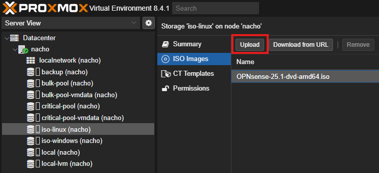
I ended up with something looking like this:
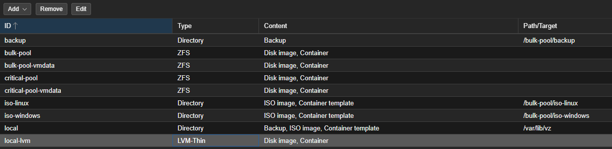
Our fancy new storage should appear on the left. I gave it a test by uploading an ISO to the iso-linux directory.
Network Planning
Your mileage will vary here depending on your hardware. Each Tiny node has a 1GB interface on which the management interface is currently bound (as well as Intel AMT), and two 10G ethernet interfaces. All lab hardware is plugged into a managed switch.
The plan is to:
- Dedicate
enp4s0f0(10G) to VM/VLAN traffic via a VLAN-aware bridge. - Dedicate
enp4s0f1(10G) to cluster communication and future ZFS replication traffic on a private subnet shared across all three nodes via the switch. - Bridge the single 1G interface
eno1to OPNsense as the WAN entry point to the network. - Deploy OPNsense as the router and firewall between all VLANs and network segments described below.
- The WAN port connects to the home modem/router, not directly to the internet. This makes the WAN effectively a LAN uplink — VLAN 10 replaces the default LAN interface in OPNsense
| VLAN ID | Network Name | Subnet | Purpose |
|---|---|---|---|
| 10 | Management | 192.168.10.0/24 |
Any management interfaces. (Dedicated 1Gb port) |
| 30 | Secure Services | 192.168.30.0/24 |
Trusted VMs: DNS, DHCP, Active Directory, etc. |
| 40 | VM Network | 192.168.40.0/24 |
General purpose trusted virtual machines. |
| 99 | Dirty (Internet) | 192.168.99.0/24 |
Untrusted zone for analysis that requires internet access. Heavily restricted from internal networks. |
| 100 | Dirty Isolated (No Internet) | 192.168.100.0/24 |
Completely untrusted zone with no internet or internal access. For malware that should be fully contained. |
[!IMPORTANT]
One major issue here is that if the OPNsense VM goes down, we will lose access to, well, everything. As this is a cyber security focused lab, I accept this in favour of the workloads being isolated from my local LAN and having access controlled by firewall. Eventually I’ll deploy a dedicated physical firewall.
[!NOTE]
Update (30/05/26): Where did VLAN 20 (Cluster Replication) go? I removed from OPNsense routing entirely. Cluster communication now runs on a dedicated private subnet (192.168.20.0/24) across all three nodes via the managed switch. This traffic never touches OPNsense. See cluster network configuration below. If you followed a previous version of this article you’ll note the bond I configured previously is gone.
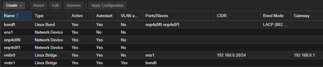
Configure Networking
[!NOTE]
vmbr0is created automatically by the Proxmox installer on whichever interface you selected during installation. The configuration steps below assume it already exists oneno1with your management IP assigned.
Datacenter > Node > System > Network > Create > Linux Bridge
- Name: vmbr1
- VLAN aware: Yes,
- Bridge ports: enp4s0f0
- No IP address/gateway
- Press Create.
Edit the enp4s0f1 device:
- IP: 192.168.20.2/24
- No gateway - direct L2 network on the switch, no routing required.
- Press Create
This interface carries Corosync heartbeat and future ZFS replication traffic between all three cluster nodes via the managed switch. It does not route through OPNsense.
Select Apply Configuration > Yes.
New interfaces change to Active. Hooray…
[!NOTE] Intel AMT shares
eno1physically and operates independently of the OS on its own IP. I reserved the AMT IPs are statically reserved in your DHCP server to prevent address conflicts. I’ve had AMT stability when running traffic from multiple VMs on the same interface as AMT before.
Deploy OPNsense
Going for the ‘reasonable’ system requirements:
- Create VM,
- Name: opnsense,
- Start at boot: Yes,
- Tags:
firewallcriticalrouterinfra, - Next > Use CD/DVD disc image file (iso). Select the ISO image we uploaded of OPNsense,
- Next > Next (Leave System at defaults),
- Storage: critical-pool-vmdata,
- Disk size: 40,
- Next,
- CPU: 1 socket / 2 cores,
- Memory: 4096,
- Next,
- Bridge: vmbr0, (for the management interface)
- Next,
- Start after created: No,
- Finish.
After creation, let’s add the second network device for VM/VLAN traffic:
- Datacenter > Node > opnsense > Hardware > Add > Network Device
- Bridge: vmbr1,
- Add.
We can now start the VM.
Install OPNsense
- Once the VM is booted, log in as
installerwith passwordopnsense. - I follow all defaults to install OPNsense.
- Change the root password.
- Complete the install and reboot.
Configuring OPNsense
[!IMPORTANT]
Before configuring I plan on adding the static WAN IP of 192.168.0.5 to connect to my modem/router. In my modem/router I specify a static route to 192.168.10.0/24 via 192.168.0.5 so that I will be able to access the configured LAN interface. By default the WAN interface will block private networks.
My installation came up on a subnet I can’t access (192.168.1.1). Login to the appliance as root with the password you just set.
- Assign interfaces (1)
- Do you want to configure LAGGs now?: n
- Do you want to configure VLANs now?: n
- Valid interfaces are presented. Checking the Hardware for the VM I obtain the MAC of bridge
vmbr0for the WAN. In this case I selectvtnet1as the WAN port. - For the LAN interface, I select
vtnet0, ourvmbr1bridge to the bond - I then press enter for the optional interface as we are finished
- Do you want to proceed? y
I then set the interface IP addresses with option 2:
- LAN (1)
- DHCP: No
- LAN IPv4:
192.168.0.13, (We’ll move it to the VLAN later, any free IP is good on your LAN) - Subnet:
24 - Upstream gateway: Enter for none
- IPv6: N
- DHCP server: N (will configure in GUI later)
- Defaults for remainder
I then repeat for the WAN interface, setting the IPv4 to 192.168.0.5. I enter 192.168.0.1 for the upstream gateway address, and select Y to use it as the name server.
[!TIP]
Initially I couldn’t get the 192.168.10.0/24 range because I had a VMware network on my workstation in that range. In Windows a quick
route printshowed any conflicting routes.
OPNsense Install Wizard
We can then access OPNsense from the LAN web interface and complete the setup wizard. Login with the root credentials you set during installation.
- Set your preferred hostname and domain.
- Set your DNS servers, I simply set
1.1.1.1and8.8.8.8for the moment. - I’ll be testing Unbound DNS in addition to my usual setup of Pi-hole + BIND. I’ll tick both Enable DNSSEC Support and Harden DNSSEC data and test this out more later.
- Replace the time server hostnames with some from your local country pool from the NTP Pool Project.
0.au.pool.ntp.org 1.au.pool.ntp.org 2.au.pool.ntp.org 3.au.pool.ntp.org - I elect to leave UTC as the time zone.
- I change the WAN interface to static and select an unused IP from my LAN (
192.168.0.5), and enter the gateway for my LAN (192.168.0.1). - I untick ‘Block private networks from entering via WAN’ as the WAN port does not have public IP address space.
- The LAN interface IP I set to DHCP to ensure we can still access the GUI until we finish our configuration.
- I skip changing the root password as it’s already done, and reload.
I then proceed to System > Firmware > Updates and update OPNsense before configuring any further.
Configuring the VLANs
| OPNsense Interface Name | VLAN Tag | Proxmox Bridge | Static IP Address | Subnet | Role |
|---|---|---|---|---|---|
| WAN | (Your ISP) | (Separate Bridge) | (DHCP or Static from ISP) | (Public IP) | Internet Connection |
PVE_MGMT (Parent: vtnet0) |
10 |
vmbr1 |
192.168.10.1 |
/24 |
Gateway for Management Interfaces |
PVE_SECUREVM (Parent: vtnet0) |
30 |
vmbr1 |
192.168.30.1 |
/24 |
Gateway for Secure Services |
PVE_VMNET (Parent: vtnet0) |
40 |
vmbr1 |
192.168.40.1 |
/24 |
Gateway for VM Network |
PVE_DIRTY_INET (Parent: vtnet0) |
99 |
vmbr1 |
192.168.99.1 |
/24 |
Gateway for Dirty (Internet) |
PVE_DIRTY_ISOLATED (Parent: vtnet0) |
100 |
vmbr1 |
192.168.100.1 |
/24 |
Gateway for Isolated Zone |
- To configure the VLANs, head to Interfaces > Devices > VLAN and click the + icon.
- Configure each VLAN with the device name
vlan0.10based on its VLAN tag, and then enter the VLAN tag and a description for its role. - Click Apply.
WAN/LAN Configuration
As my WAN interface is plugged into a modem/router, I want to disable the IPv4 gateway rules otherwise we may cause some asymmetric routing. In Interfaces > WAN > Static IPv4 configuration, change IPv4 gateway rules to Disabled. Save.
The LAN interface comes with anti-lockout rules to prevent locking yourself out of the firewall interface. We add a firewall rule to the WAN interface as this is basically our interface back to the main LAN. You could lock it down here to just a single workstation or device if you wanted.
Firewall > Rules > WAN > Click Add (+):
- Interface: WAN,
- Protocol: TCP,
- Source: WAN net, (192.168.0.0/24)
- Destination: This Firewall,
- Destination port range: HTTPS,
- Description: WAN/LAN to Firewall HTTPS,
- Save.
In the Firewall > Rules > LAN rules if we click on the small disclosure triangle below the add rule button we can see the default anti lockout rules. Let’s add a specific one, soon the WAN traffic will be the only way into the firewall, so we’ll need to permit the WAN network into this LAN (soon to be VLAN10 management VLAN) network. We’ll leave it broader in the beginning so we don’t break anything.
- Interface: LAN,
- Protocol: TCP,
- Source: WAN net,
- Destination: This Firewall,
- Destination port range: HTTPS,
- Description: WAN/LAN access to Management VLAN HTTPS,
- Save. Apply Configuration.
Assign VLANs to Interfaces
At this point we will want to be working off the WAN IP 192.168.0.5 as we are about to change the 192.168.0.13 LAN management address to the new management VLAN.
-
Head to Interfaces > Assignments,
-
Change LAN interface to the vlan0.10 device. Save. We will change the firewall to the new management VLAN,
-
Head to Interfaces > LAN,
-
Description > PVE_MGMT,
-
IPv4 Address:
192.168.10.1/24. Save. Apply changes.
[!NOTE]
If all went well with our firewall rules and our static route, we should be able to access the OPNsense interface on
https://192.168.10.1andhttps://192.168.0.5.
- Under Assign a new interface, work through each ‘Device’ and add the interface name into the description.
- Click Save. We should end up with something like:
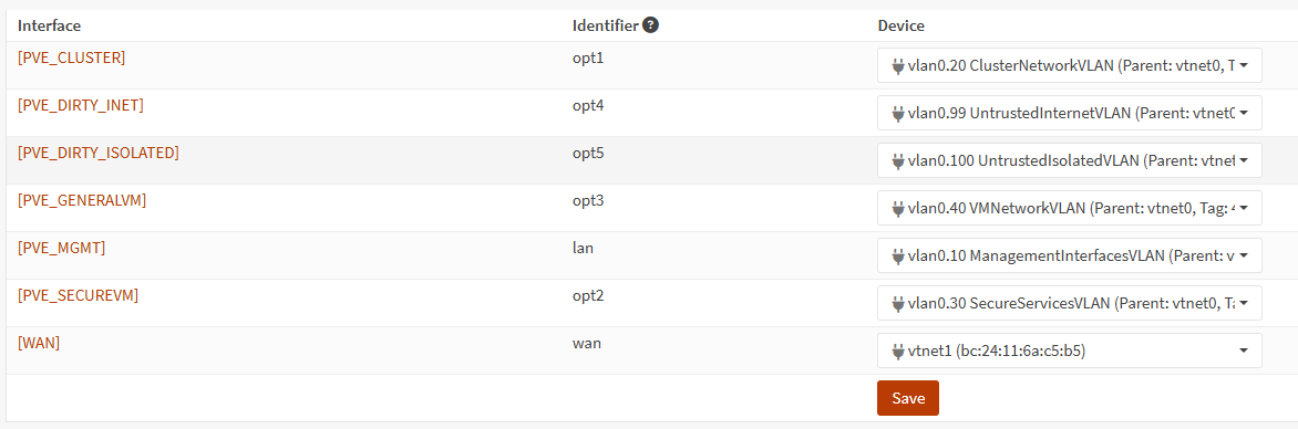
-
Now work through each interface and check Enable Interface.
-
Add a IPv4 Configuration Type of Static IPv4 to each interface, setting the address as per our table above. Don’t forget the
/24. Save and Apply changes. -
Head to Interfaces > Overview and we should see something like:
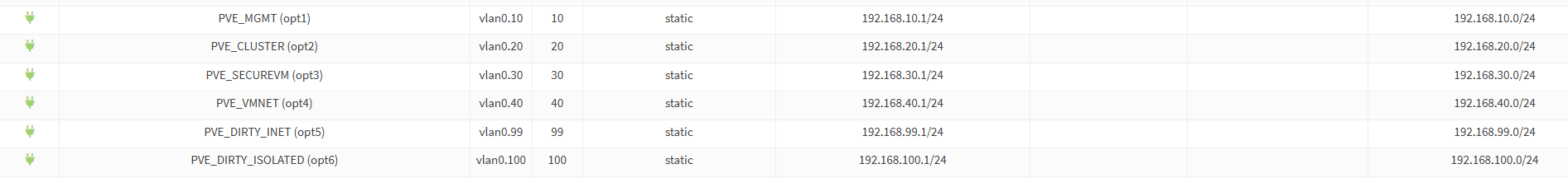
Enable DHCP for our Interfaces
Head to Services > ISC DHCPv4 > [PVE_SECUREVM].
I don’t enable DHCP on the cluster interface as it should only have a couple of statically set IP addresses to maintain the Proxmox cluster.
We’ll start with the secure VM interface as an example.
- Click Enable DHCP server on the PVE_SECUREVM interface,
- Enter a range of
192.168.30.60to192.168.30.200, - Save.
- Repeat for other DHCP enabled zones, such as PVE_VMNET, and PVE_DIRTY_INET.
Add Firewall Rules
While there will be much configuration to be done, initially let’s put in a protective rule for our isolated segment:
Firewall > Rules > PVE_DIRTY_ISOLATED. New rule…
- Action: Block,
- Direction: out,
- Protocol: IPv4+IPv6,
- Source: PVE_DIRTY_ISOLATED net,
- Destination: any,
- Save. Apply Changes.
Firewall > Rules > PVE_MGMT. New rule…
- Action: Block,
- Direction: in,
- Protocol: IPv4+IPv6,
- Source: PVE_DIRTY_ISOLATED net, PVE_DIRTY_INET net, PVE_GENERALVM net, PVE_SECUREVM net,
- Destination: any,
- Save. Apply Changes.
This is a small start to preventing anything from leaving our isolated network, and any of the other VLANs from accessing the management network.
Initial Configuration Complete
- While Proxmox and OPNsense are up and running, we have flexible network lab segments which we can isolate and restrict with ease.
- There are Terraform and Ansible modules for OPNsense that we can use to add rules and configurations via Infrastructure as Code.
- We must take care not to lock ourselves out of the appliance either through misconfigurations or environment changes.
- Our WAN and PVE_MGMT anti-lockout rule should help prevent this. Note we would not do this on our WAN interface if it was directly connected to public IP address space.
- There are some risks with this setup as described, particularly around resilience, but we accept them.
- Next steps are to configure our second Proxmox node and quorum device.
Outbound Internet Note
If you create a VM and want it to have outbound connectivity from a VLAN it will need a NAT rule. For example for the PVE_MGMT VLAN 10:
- Firewall > NAT > Outbound,
- Hybrid outbound NAT rule generation,
- Save,
- Add rule (+),
- Interface: WAN,
- Source address: PVE_MGMT,
- Translation / target: Interface address.
Otherwise the Interwebz will not be able to route the traffic back to the original source. For example, this would change the source address from 192.168.10.60 to 192.168.0.5.
Configure additional outbound NAT rules for other VMs as they require Internet access. We’ll set up a proxy later.
What’s Next?
In the next article we’ll aim to:
- Build the second node and third quorum node.
- Create the Proxmox cluster.
- Join the newly deployed nodes to the cluster.